Design an amplifier with an operating power gain of 8 dB.
In a 50 ![]() system, the characteristics of a microwave transistor measured at 2.0 GHz is
shown as the following.
system, the characteristics of a microwave transistor measured at 2.0 GHz is
shown as the following.
![]()
![]()
Design an amplifier with an operating power gain of 8 dB.
Solution
![]()
![]()
This device is potentially unstable.
![]()
![]()
![]()
The input stability circle on ![]() plane has
plane has
![]()
![]()
![]()
The corresponding constant operating power gain has
![]()
![]()
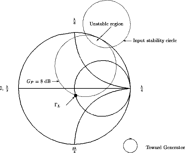
We put both the constant operating power gain and input stability circles as shown in Figure 23.
Clearly, the chosen ![]() should stay away from the input stability circle and must be
on the constant operating power circle. Let's say, we choose
should stay away from the input stability circle and must be
on the constant operating power circle. Let's say, we choose ![]() . Then we can
find the input reflection coefficient
. Then we can
find the input reflection coefficient
![]()
If we use conjugate matching at the input,
![]()

Figure 23: The constant gain and input stability circles drawn
on ![]() plane
plane
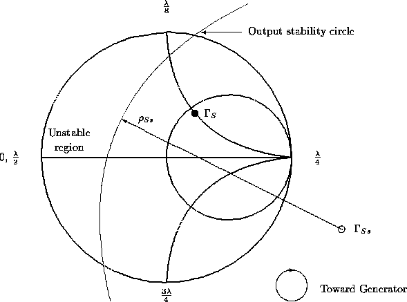
We need to examine this ![]() to see whether it is in the stable region
by means of output stability circle in Figure 24. The output stability circles has
to see whether it is in the stable region
by means of output stability circle in Figure 24. The output stability circles has
![]()
![]()

Figure 24: The output stability circle drawn on ![]() plane
plane
From Figure 24, ![]() is in the stable region. So
we can accept
is in the stable region. So
we can accept ![]() and
and ![]() as the design
value. Otherwise, we need to choose another value of
as the design
value. Otherwise, we need to choose another value of ![]() until the corresponding
until the corresponding ![]() is in the stable region. The above procedures are used for designing for a specified
power gain. If the objective is to design for low noise figure, we should
start with
is in the stable region. The above procedures are used for designing for a specified
power gain. If the objective is to design for low noise figure, we should
start with ![]() in the beginning. Use the output stability circle to check
whether the
in the beginning. Use the output stability circle to check
whether the ![]() is in the stable region. If
is in the stable region. If ![]() is in
the stable region, choose
is in
the stable region, choose ![]() , otherwise choose a
, otherwise choose a
![]() in the stable region with lowest noise figure with the aid of constant noise
figure circle. For a given
in the stable region with lowest noise figure with the aid of constant noise
figure circle. For a given ![]() , find the corresponding conjugate matched load
reflection coefficient
, find the corresponding conjugate matched load
reflection coefficient ![]() . Check its stability with the input stability circle.
Repeat the process until both
. Check its stability with the input stability circle.
Repeat the process until both ![]() and
and ![]() are in the stable regions.
are in the stable regions.