Introduction to Quartz Frequency Standards - Interactions among the Influences on Stability
![]() Forward to "Oscillator Comparison and Selection".
Forward to "Oscillator Comparison and Selection".
![]() Back to "Other Effects on Stability".
Back to "Other Effects on Stability".
![]() Back to the tutorial's table of contents.
Back to the tutorial's table of contents.
The various influences on frequency stability can interact in ways that lead to erroneous test results if the interfering influence is not recognized during testing. For example, building vibrations can interfere with the measurement of short-term stability. Vibration levels of 10-3 g to 10-2 g are commonly present in buildings. Therefore, if an oscillator's acceleration sensitivity is 1 x 10⁻⁹/g, then the building vibrations alone can contribute short-term instabilities at the 10-12 to 10-11 level.
The 2-g tipover test is often used to measure the acceleration sensitivity of crystal oscillators. Thermal effects can interfere with this test because, when an oscillator is turned upside down, the thermal gradients inside the oven can vary due to changes in convection currents [29]. Other examples of interfering influences include temperature and drive-level changes interfering with aging tests; induced voltages due to magnetic fields interfering with vibration-sensitivity tests; and the thermal-transient effect, humidity changes, and the effect of load-reactance temperature coefficient interfering with the measurement of crystal units' static f vs. T characteristics.
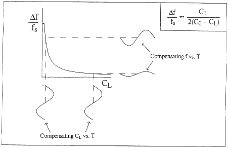
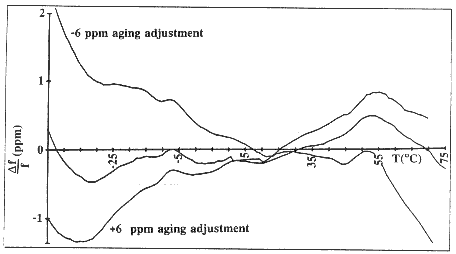
An important effect in TCXOs is the interaction between the frequency adjustment during calibration and the f vs. T stability [42]. This phenomenon is called the trim effect. In TCXOs, a temperature-dependent signal from a thermistor is used to generate a correction voltage that is applied to a varactor in the crystal network. The resulting reactance variations compensate for the crystal's f vs. T variations. During calibration, the crystal's load reactance is varied to compensate for the TCXO's aging. Since the frequency versus reactance relationship is nonlinear' the capacitance change during calibration moves the operating point on the frequency versus reactance curve to a point where the slope of the curve is different, which changes the compensation (i.e., compensating for aging degrades the f vs. T stability). Figure 32 shows how, for the same compensating CL VS. T, the compensating f vs. T changes when the operating point is moved to a different CL. Figure 33 shows test results for a 0.5 ppm TCXO that had a +6 ppm frequency-adjustment range (to allow for aging compensation for the life of the device). When delivered, this TCXO met its 0.5 ppm f vs. T specification; however, when the frequency was adjusted + 6 ppm during testing, the f vs. T performance degraded significantly.

Figure 32. Change in compensating frequency versus temperature due to CL change.

Figure 33. Temperature-compensated crystal oscillator (TCXO) trim effect.
![]() Forward to "Oscillator Comparison and Selection".
Forward to "Oscillator Comparison and Selection".
![]() Back to "Other Effects on Stability".
Back to "Other Effects on Stability".
![]() Back to the tutorial's table of contents.
Back to the tutorial's table of contents.