Introduction to Quartz Frequency Standards - Acceleration Effects
![]() Forward to "Magnetic-Field Effects".
Forward to "Magnetic-Field Effects".
![]() Back to "Warmup".
Back to "Warmup".
![]() Back to the tutorial's table of contents.
Back to the tutorial's table of contents.
Acceleration changes a crystal oscillator's frequency [29]. The acceleration can be a steady-state acceleration, vibration, shock, attitude change (2-g tipover), or acoustic noise. The amount of frequency change depends on the magnitude and direction of the acceleration A, and on the acceleration sensitivity of the oscillator G. The acceleration sensitivity is a vector quantity. The frequency change can be expressed as

When an oscillator is rotated 180° about a horizontal axis, the scalar product of the gravitational field and the unit vector normal to the initial "top" of the oscillator changes from -1 g to +1 g, i.e., by 2g. Figure 25 shows actual data of the fractional frequency shifts of an oscillator when the oscillator was rotated about three mutually perpendicular axes in the earth's gravitational field. For each curve, the axis of rotation was horizontal. The sinusoidal shape of each curve is a consequence of the scalar product being proportional to the cosine of the angle between the acceleration-sensitivity vector and the acceleration due to gravity [29].
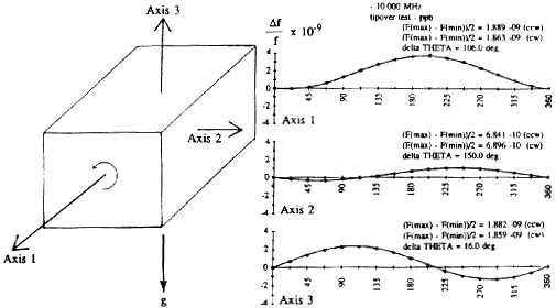
Figure 25. 2-g tipover test (Df vs. attitude about three axes).
In the frequency domain, the modulation results in vibration-induced sidebands that appear at plus and minus integer multiples of the vibration frequency from the carrier frequency. Figure 26 shows the output of a spectrum analyzer for a 10 MHz, 1.4 x 10⁻⁹/g oscillator that was vibrated at 100 Hz and 10 g. For sinusoidal vibration, the "sidebands" are spectral lines. When the frequency is multiplied, as it is in many applications, the sideband levels increase by 20 dB for each 10X multiplication. The increased sideband power is extracted from the carrier. Under certain conditions of multiplication, the carrier disappears, i.e., all the energy is then in the sidebands.
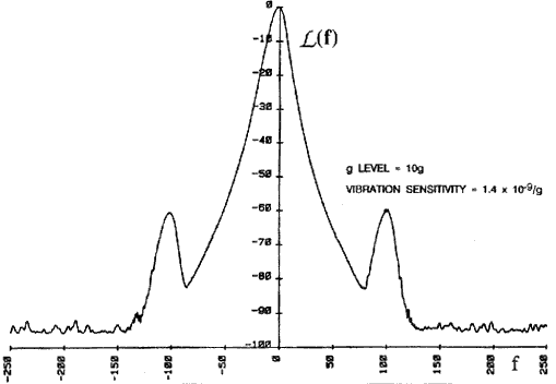
Figure 26. Vibration-induced "sidebands" (i.e., spectral lines).
The acceleration sensitivity can be calculated from the vibration-induced sidebands. The preferred method is to measure the sensitivity at a number of vibration frequencies in order to reveal resonances. Figure 27 shows an example of the consequence of a resonance in an OCXO, at 424 Hz. This resonance amplified the acceleration sensitivity 17-fold.
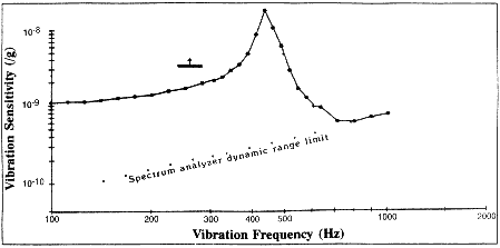
Figure 27. Resonance in the acceleration sensitivity vs. vibration frequency characteristic.
The effect of random vibration is to raise the phase-noise level of the oscillator. The degradation of phase-noise can be substantial when the oscillator is on a vibrating platform, such as on an aircraft. Figure 28 shows a typical aircraft random-vibration specification (power spectral density [PSD] vs. vibration frequency) and the resulting vibration-induced phase-noise degradation. Acoustic noise is another source of acceleration that can affect the frequency stability of oscillators.
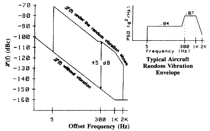
Figure 28. Random-vibration-induced phase-noise degradation.
The peak phase excursion, fpeak, due to sinusoidal vibration is


Upon frequency multiplication, both fpeak and F increase by the multiplication factor. For example, if G A = 1 x 10⁻⁹, f0 = 10 MHz and fV = 10 Hz, then fpeak = 1 x 10⁻³ radian. If this oscillator's frequency is multiplied to 10 GHz, e.g., in a radar system, then at 10 GHz, fpeak = 1 radian. Such large phase excursions can be catastrophic to many systems.
Figure 29 shows how the probability of detection for a coherent radar system varies with the phase noise of the reference oscillator [30]. The phase noise requirement for a 90% probability of detection of a 4km/hr target is -130 dBc per Hz at 70 Hz from the carrier, for a 10 MHz oscillator. Such a phase noise is well within the capability of 10 MHz oscillators, provided that the oscillators are in a quiet environment. However, when the oscillators are on a vibrating platform, such as an airborne radar system, the phase noise of even the best available oscillators (as of 1992) is degraded by an amount that reduces the probability of detection to zero.
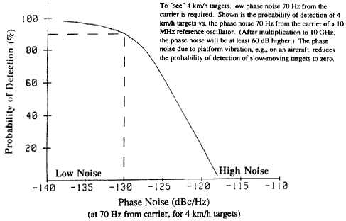
Figure 29. Coherent radar probability of detection as a function
of reference oscillator phase noise.
During shock, a crystal oscillator's frequency changes suddenly due to the sudden acceleration, as is illustrated in Figure 30 The frequency change follows the expression above for acceleration-induced frequency change except, if during the shock some elastic limits in the crystal's support structure or electrodes are exceeded (as is almost always the case during typical shock tests), the shock will produce a permanent frequency change.
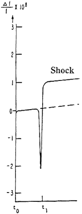
Figure 30. The effect of a shock at t=t1 on oscillator frequency.
Permanent frequency offsets due to shock can also be caused by changes in the oscillator circuitry (e.g., due to movement of a wire or circuit board), and the removal of (particulate) contamination from the resonator surfaces. Resonances in the mounting structure will amplify the shock-induced stress.
If the shock level is sufficiently high, the crystal will break; however, in applications where high shock levels are a possibility, crystal units with chemically polished crystal plates can be used. Such crystals can survive shocks in excess of 30,000 g and have been fired successfully from howitzers [12,31].
![]() Forward to "Magnetic-Field Effects".
Forward to "Magnetic-Field Effects".
![]() Back to "Warmup".
Back to "Warmup".
![]() Back to the tutorial's table of contents.
Back to the tutorial's table of contents.